Simple
Circuit – Analysis with MatlabIn the
following exercise we are going to analyze a simple circuit with
Matlab. This
is the logic next step or a continuation of the nodal analysis example
that we
previously worked on the page dedicated to Nodal Analysis using the KCL.
|
|
This
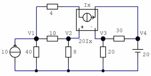
circuit contains more components: 6 resistors (in ohms), a current
source (in
amperes), a voltage source (in volts) and a voltage source that
produces its
voltage depending on a current going through another branch of the
circuit (that’s
called a current-controlled voltage source, or CCVS). |
The
schematic for our example is as follows:

This is
the symbol of the constant current source:

In
particular, the current through this source is 10 A.
This is
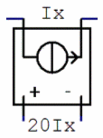
the symbol of the current-controlled voltage source:
In
particular, this source is creating a voltage of 20 times the current
Ix, that
goes through the top branch of the circuit, that is, through the 4-ohm
resistor.
Our
goal is to discover or calculate the values of the voltages on the
shown four
nodes, V1 to V4.
Proposed
Solution
We are
going to solve a linear system that represents our circuit. We have 4
variables
and can study 4 nodes (the remaining node is the reference node or
ground), and
we are going to solve the linear equation YV = I by using the left
division
available in Matlab, V = Y\I, where Y is the square matrix (4 × 4) of coefficients of the
unknowns in our system, V is the 4-element column vector representing
the nodes,
and I is the 4-element column vector of constants on the right of the
system.
Each row of our matrices is going to summarize the analysis of each
node, while
each column is going to contain the coefficients of the unknowns.
Kirchhoff’s
current law (KCL) states that for any electrical circuit, the algebraic
sum of
all the currents at any node in the circuit equals zero.
Analysis
At
node
1, we have
Current
going to it, 10 A.
Currents
going out from it, V1/40, (V1 - V2)/10, and (V1 - V4)/4
In
mathematics that means:
10 =
V1/40 + (V1 - V2)/10 + (V1 - V4)/4
Rearranging
the above numbers, the first row of our Y matrix is:
Y(1, :)
= [(1/40 + 1/4 + 1/10) (-1/10) 0 -1/4]
And the
first element of our column I is:
I(1) =
10
At
nodes 2 and 3, we can see that
V2 – V3
= 20Ix, but we also know that Ix = (V1 - V4)/4
that
means that
V2 – V3
= 20(V1 - V4)/4
and we
conclude that the second row of our Y matrix is:
Y(2, :)
= [5 -1 1 -5]
The
second element of our column I is
I(2) =
0
From supernodes 2 and 3,
we get
(V2 – V1)/10 + V2/8 + V3/20 + (V3 - V4)/30 = 0
This produces our third
row of the Y matrix:
Y(3, :) = [-1/10 (1/10 + 1/8) (1/20 + 1/30) -1/30]
The third element of I is
I(3) = 0
And at node 4, we
easily see that V4 = 20.
This means that
Y(4, :) = [0 0 0 1]
and
I(4) = 20
Because of the above
explanation, our Y matrix is
Y = [
(1/40 +
1/4 + 1/10) -1/10 0 -1/4
5
-1 1 -5
-1/10
(1/10 + 1/8) 1/20 + 1/30 -1/30
0 0 0 1]
Our constant vector on
the right of our system is
I = [5 0
0 20]’
And, thanks to the left
division, we can easily solve our
simple circuit, by just typing
V = Y\I
Nodal voltages V1, V2,
V3, V4 are
V =
36.2215
35.8306
-
45.2769
20
From
'Simple Circuit' to home
From 'Simple Circuit' to
'Electrical Calculations'


|


